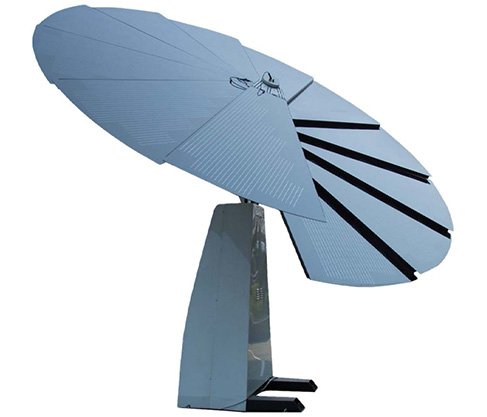
PV Sunflower
Triple axis tracking photovoltaic sunflower is a comprehensive power, inverter, and storage “trinity” of solar power systems.
The system adopts the astronomical tracing algorithm and realizes 24-hour automatic tracking of the sun’s position, relative to the conventional solar power system efficiency increases by about 40%, energy storage systems, the device can run independently of the power grid, and meet the demand of the use of various occasions.
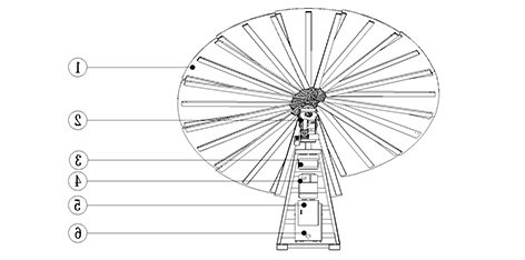
| ① Solar blade module | ② Triple axis slewing tracking support |
| ③ Switch Box | ④ All in one optical storage machine |
| ⑤ Control System | ⑥ Energy Storage Battery |
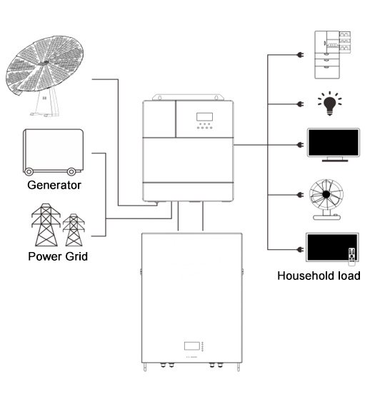
1. Solar modules: convert light energy into direct current energy, charge the battery through the integrated machine, or directly invert into ac power to power the load.
2. Mains or generator: Connect to the AC input terminal to power the load and charge the battery.
If there is no power supply or generator, the system can run normally, and the load power is provided by batteries and photovoltaic modules.
3. Energy storage battery: The role of the energy storage battery is to ensure the normal power consumption of the system load when solar energy is insufficient and there is no electricity supply.
4. Household load: it can be connected to various household and office loads, including refrigerators, lamps, TV sets, fans, air conditioners, and other AC loads.
5. Inverter: energy conversion device of the whole system.
The specific system cable connection mode depends on actual application scenarios.
| Specification Parameter | |||
| Model | CD-225M-42 | Rated Power | 225W±5% |
| Operating Voltage | 22.5V | Working Current | 10A |
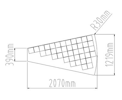
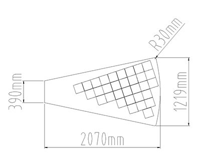
| Efficiency | ≥21.6% | Max Size | 2070*1228*5mm |
| Max System Voltage | 1000V DC | Operating Temperature | -40~+85℃ |
| Power Temperature compensation coefficient | -0.43%/℃ | Current Temperature Compensation Coefficient | 0.08%/℃ |
| Voltage Temperature Compensation Coefficient | -0.37%/℃ | Service Life | ≥20years |
| Power Warranty | Not less than 90% in ten years | Max Hail Impact Required | 25mm;23m/s |
| STC(standard test conditions) : irradiance 1000W/㎡, battery temperature 25℃, spectrum AM1.5 | |||
| Specification Parameter | |||
| Model |
CD-170M-30 |
Rated Power |
170W±5% |
| Operating Voltage | 17V | Working Current | 10A |
| Efficiency | ≥21.6% | Max Size | 2070*1228*5mm |
| Max System Voltage | 1000V DC | Operating Temperature | -40~+85℃ |
| Power Temperature compensation coefficient | -0.43%/℃ | Current Temperature Compensation Coefficient | 0.08%/℃ |
| Voltage Temperature Compensation Coefficient | -0.37%/℃ | Service Life | ≥20years |
| Power Warranty | Not less than 90% in ten years | Max Hail Impact Required | 25mm;23m/s |
| STC(standard test conditions) : irradiance 1000W/㎡, battery temperature 25℃, spectrum AM1.5 | |||
|
Overall System Specification Parameters |
||
|
Model |
CD-225M-42 |
CD-170M-30 |
|
Quantity |
11pcs |
1pcs |
|
Connection Method |
12pcs Series |
|
|
System Operation Voltage |
265V DC |
|
|
System Operation Current |
10A DC |
|
|
System Power |
2645W |
|
|
Max System Voltage |
1000V DC |
|
|
STC(standard test conditions) : irradiance 1000W/㎡, battery temperature 25℃, spectrum AM1.5 |
||
|
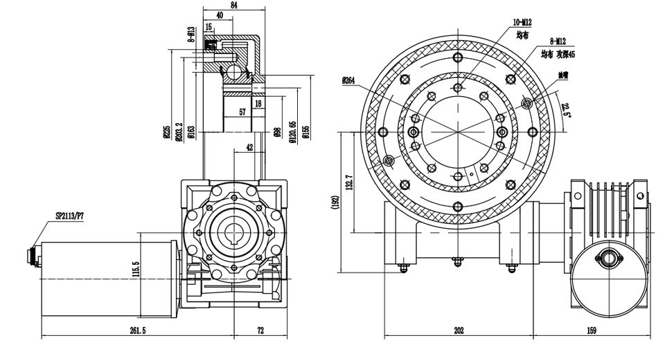
Rotary speed reducer performance parameters |
|
| Rated output speed | 0.21 rpm |
| Rated output torque | 1500 N.m |
| Max output torque | 3000 N.m |
| Overturning moment | 13.6 kN.m |
| Keep the moment | 10 kN.m |
| Axial load | 32 kN |
| Radial load | 28 kN |
| Reduction ratio | 71:1 |
| Precision grade | ≤0.1° |
| Applicable ambient te mpe rature | -30-+80℃ |
|
Dc brush RV reduction motor |
|
| Rated voltage | 24 VDC |
| Rated current | <9A |
| Rated output speed | 15 rpm |
| Protection grade | IP65 |
3.3.1 Basic Parameter
| Model HF4830S60-H | |||
| Mains Mode | |||
| Rated Input Voltage | 220/230Vac | Input Voltage Range |
(170Vac~280Vac) ±2% (90Vac-280Vac)±2% |
| Frequency | 50Hz/ 60Hz | Frequency Range |
47±0.3Hz ~ 55±0.3Hz (50Hz); 57±0.3Hz ~ 65±0.3Hz (60Hz); |
| Overload/Short Circuit Protection | Breaker | Efficiency | >95% |
| Conversion Time (bypass and inverter) | 10ms (typical value) | Max Bypass Overload Current | 60A |
|
Inverter mode |
|||
| Output Voltage Waveform | Pure sine wave | Rated Output Power | 3000 |
| Rated Output Voltage | 230Vac | Output Voltage Error | ±5% |
| Output Frequency Range |
50Hz ± 0.3Hz 60Hz ± 0.3Hz |
Efficiency | >90% |
| Overload Protection |
(102%<Load<125%) ±10%: Error reported and output turned off after 5 minutes; (125%<load<150%) ±10%: error reported and output turned off after 10 seconds. Load > 150% ±10%: error reported and output turned off after 5 seconds. |
Peak Power | 5000VA |
| Bypass Breaker Specification | 40A | Rated Battery Input Voltage | 48V( Minimum starting voltage 44V) |
|
Mains Charging |
|||
|
Battery Type |
Lead-acid battery or Lithium battery |
Maximum Charging Current |
60A |
|
Charging Current Error |
± 5Adc |
Charging Voltage Range |
40 –60Vdc |
|
Breaker Specification |
40A |
Overcharge Protection |
Alarm and charge off after one minute. |
|
Solar Charging |
|||
|
Max PV Open Circuit Voltage |
500Vdc |
PV Operating Voltage Range |
120-500Vdc |
|
Max Solar Power |
3000W |
Battery Voltage Range |
40-60Vdc |
|
Max Output Power |
4200W |
Solar Charging Current Rang |
0-60A |
|
Charging Short Circuit Protection |
Blown Fuse |
Wiring Protection |
Reverse Connection Protection |
|
Certification Specifications |
|||
|
Certification Specifications |
CE(IEC62109) 、RoHs |
EMC Certification Level |
EN61000 |
|
Operation Temperature Range |
-15°C to 55°C |
Storage Temperature Range |
-20°C ~ 60°C |
|
Humidity Range |
5% to 95%(Three protection) |
Noise |
≤60dB |
|
Heat Dissipation |
Forced air cooling,adjustable air speed. |
Communication Interface |
USB/RS485(Bluetooth/WiFi/GPRS)/Dry Node Control |
|
Size |
426mm*332mm*123mm |
Weight |
9.7 |
|
Protection Level |
IP 20 |
||
3.3.2 Charging mode
1. Photovoltaic priority: PV priority charging, only when the PV fails to start utility charging. Make full use of solar power generation during the day and switch to utility charging at night, which can maintain battery power and is used in areas where the grid is relatively stable and electricity prices are more expensive.
2. Mains priority: Manpower charges the battery first, and PV charging is activated only when utility power is not effective.
3. Hybrid charging: PV and utility power are mixed, with priority PV MPPT charging, and utility power replenishment when PV energy is insufficient. When the PV energy is sufficient, the utility power stops charging. This way of charging is the fastest, suitable for areas with the unstable power grid, and can provide sufficient backup power supply at any time.
4. Photovoltaic charging only (Only Solar): photovoltaic charging only, without starting utility charging. This way is the most energy-saving way, battery power are from solar energy, usually used in areas with good lighting conditions.
1. PV priority mode: PV and battery supply power to the load, diversified charging mode, and output mode can be selected. When the PV priority mode is selected, it can maximize the use of green solar energy and realize energy saving and emission reduction. Switch to the utility power supply when PV is not effective. This mode maximizes the use of solar energy, while maintaining battery power, and is suitable for areas with relatively stable power grids.
2. The utility priority mode: switch to an inverter power supply only when utility power is invalid, equivalent to backup UPS, used in areas with an unstable power grid.
3. Inverter priority mode: Switch to utility power only when the battery is under-voltage. This mode makes maximum use of DC power and is used in areas with stable power grids.
